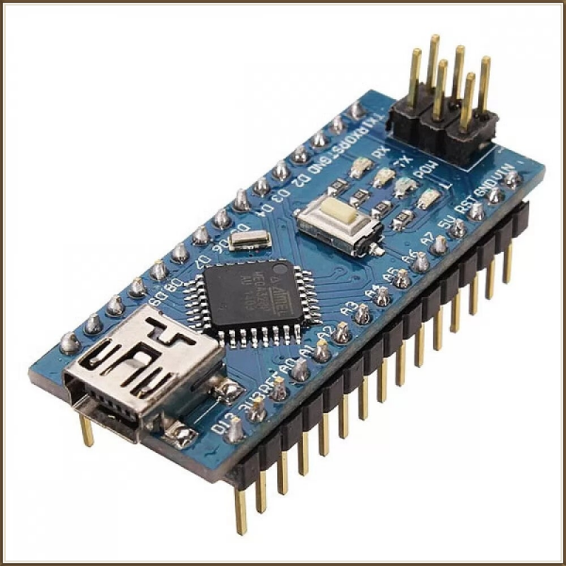
Arduino Nano v3
The Arduino Nano 3 board is based on an Atmel ATmega328 microcontroller. Its 32 Kb memory and I/O make this circuit ideal for embedded systems or applications requiring multitasking.
It is an integrated circuit that processes the information it receives and triggers actions according to the program it has received.
The Arduino Nano can be powered via:
- USB connection;
- unregulated external power supply 6-20 V (pin 30);
- 5 V regulated external power supply (pin 27).
The power source providing the best voltage will be selected as the power source by the board.
USB/serial interface
The ATMega328 microcontroller is programmed with Arduino IDE software. It contains a bootloader that enables the program to be modified directly by plugging it into a computer's USB port. It is via this connection that the program is uploaded to the microcontroller. It is also via this cable that the Arduino can send information back to the computer.
From the computer's point of view, the Arduino board is a simple peripheral for which it is therefore necessary to install drivers in order to communicate with it.
Features
- Atmel ATmega328 microcontroller ;
- Operating voltage 5V ;
- Recommended input voltage 7-12 V (max 6-20 V) ;
- Clock frequency 16 MHz ;
- Recommended current per pin 20 mA (max 40 mA) ;
- Cumulative current of all pins 200 mA ;
- Consumption at rest 19 mA ;
- 14 digital I/O pins (including 6 PWM) ;
- 8 analog input pins ;
- Flash memory 32 KB of which 2 KB used by the boot loader ;
- 2 KB SRAM ;
- 1 KB EEPROM ;
- Dimensions 45 x 18 x 18mm ;
- Weight 7g.
Top view

Bottom view

Pinout of the Arduino Nano
Some spindles have special functions:
- Serial link : 0 (RX) and 1 (TX). Used to receive (RX) and transmit (TX) serial data.
- External Interrupts : 2 and 3. These pins can be configured to trigger an interrupt on a low value, rising or falling edge, or value change.
- PWM : 8-bit PWM output on pins 3, 5, 6, 9, 10 and 11 (Pulse Width Modulation)
- SPI : 10(SS), 11(MOSI), 12(MISO), 13(SCK) These pins support communication with SPI devices.
- LED 13 : Onboard LED connected to digital pin 13.
-
Reset : Go low to restart the microcontroller electronically.
-
AREF. : Reference voltage for analog inputs.
-
I2C buses : 4 (SDA) and 5 (SCL). Support for I2C communication allowing connection of up to 127 devices.
-
Digital Inputs/Outputs : Each of the Nano's 14 digital pins can be used as an input or output and operates at 5 volts. Each pin can supply or receive a maximum of 40mA (note the cumulative current is limited to 200mA for all pins) and has an internal 20-50K pull-up resistor. This pull-up resistor connects by programming.
-
Analog inputs : The card has 8 inputs (A0 to A7), which can accept an analog voltage between 0 and 5 V.
To measure analog voltage, the Arduino Nano board uses an analog-to-digital (A/D) converter with 10-bit resolution, returning the measurement result as an integer between 0 and 1023.
All analog pins (except pins 6 and 7) can be used as digital pins.
Programming
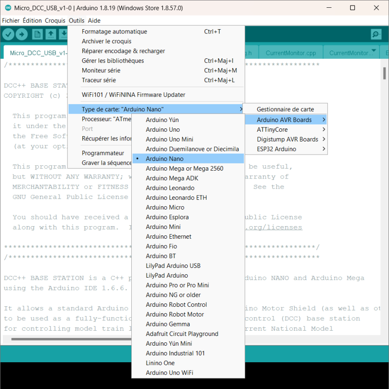
The microcontroller is programmed using the Arduino IDE. Arduino Nano drivers are installed natively in the IDE. Before uploading a program, simply make sure you have selected the correct board type (see below).
When using a new board for the first time, it's a good idea to carry out a function test to check the entire process of updating your Arduino Nano board:
- Connect the board to the computer via the USB cable;
- In the IDE, load the "Blink.ino" program directly from the file menu:

- From the "Tools" menu, select the correct processor version :

If the Nano's LED flashes, your Arduino board is ready for its final program !
Possible uses in model railroading
- Micro central DCC.
- A lot of assemblies requiring automation are based on Arduino Nano cards (DCC decoder, level crossing management, train speed measurement, etc...).


