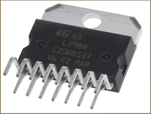
L298N - Double H-bridge

The L298N integrated circuit consists of two transistor bridges (an H-shaped bridge, hence the name). The most common use for this type of bridge is to drive a low-power DC motor using PWM (Pulse Width Modulation) voltage.
This double H-bridge can therefore control either two DC motors or one stepper motor. The two bridges can also be connected in parallel for double the power.
Principle of the H-bridge
The H-bridge is the name given to this transistor configuration because, on the schematic, it resembles the letter "H". The bipolar power transistors used in this component can be represented as switches (Figure 1). They are controlled by 5V-powered logic gates.
This component therefore requires two separate power supplies:
- 5 V supply for the control logic;
- the load power supply, between 5 and 46 V.
Two control lines drive the bridge. Each is on load on one side of the bridge (left or right), and the signal arriving on the high side is inverted on the control of the power transistor on the low side. So there's no risk of creating an internal short circuit, whatever the signal applied to the controls (Figure 2).
Figures 3 and 4 show the principle of supplying the load in one direction or the other, depending on the level of the two controls.
There is another configuration (not shown here) in which the bridge is controlled with the same level on both control lines. This configuration is used for rapid braking of the motor connected to the load, as it allows the development of an induced current in the motor.
Figure 2: the bridge is controlled by two logic controls (one for each side of the assembly). The control level is reversed for the lower part of the bridge.
In order to simplify the explanations of this component, the PWM commands coupled to the two control lines described above are not detailed here. Pulse-width modulation is used to artificially modify the VCC level applied to the load, thereby altering the motor's rotation speed.
Output current available
Each bridge can deliver up to 2 A continuously, peaking at 3 A for very short periods. The two bridges can also be "coupled" to deliver 4 A output to the load.
Such currents inevitably require a cooling system, as switching power transistors means dissipating a lot of heat. As soon as the L298N is used for more than a few hundred mA, it will need to be fitted with a cooler.
Generate a DCC signal
For model railroading, this component will also generate the DCC power signal that will be applied to the rails, as in the micro DCC control unit assembly.
In this case, the bridge's VCC power supply is 15 V (or 18 V for HO) and the rails are connected to the load. By applying the control principle described above to a signal corresponding to the DCC standard, this component is capable of powering a rail network capable of controlling more than a dozen locomotives (depending on their power consumption) equipped with digital decoders, as well as accessories such as points.


